Wasn't too sure what to expect when I arrived at the event and had packed away some projects back at the hack-space after the maker faire at the weekend. I was a little last minute in thinking about attending the event so grabbed my recently 3D printed lamp to present at this event. Over the last year I have spent many hours by the Build Brighton 3D printers producing items from designs, fixing and using the Build Brighton 3D printer, so users can arrive, get a small induction to 3D printing and then print their own design. I came across a nice looking lamp design, which I found on this site makershop.co, it's also called My Lamp . The design is also available on Thingiverse presented by user called Teece and released under the CC BY-SA 3.0 licence.

This sparked an idea, rather than having 3D print items which are mundane and don't also have a purpose. I should be able to make something with this, so I started printing out the design; it's made up of about 7 pieces, the shade was too tall (143mm) for the printer. So used netfabb to perform a Z cut so that the part was under the printer's 100mm height limit. This also reduced the print time for the shade. The printer's settings was 190-200 degrees C (hot end) and 60 degrees (bed temp) with a 0.2mm layer height. As the shade was printed in 2 parts. I needed some way of joining them; first thought was 2 part epoxy which worked OK, there was a slight step as it was hard to line up but I was able to make it look presentable with a small file. There was also a suggestion it would have been better to use "ABS glue" (small bits of ABS filament dissolved in acetone) to make a smooth paste, which when applied and the acetone evaporates, the ABS holds the parts together.
I wasn't able to source the same lead/led set-up used in the post but was aware due to heat produced by a normal 240v 60W incandescent lamp that I would need to use LED's. I did think about using LED's bulbs and CFL's but didn't have the funds available to buy them or the time to wait for delivery.
So the thinking was this is going to be a bedside lamp with a switch and use cheap, easy to get LED's, get a high mA value should give good amount of light, also wanted the light produced to be a "warm white" as this will not attract the flying bugs or insects to the light, they hate it so fly away from the light.
During the research stage I found these 10mm 20mA 11000-15000 mcd LED's 30 degree viewing angle available from Phenoptix. Those should provide a good amount of light, also came across this Touch IC
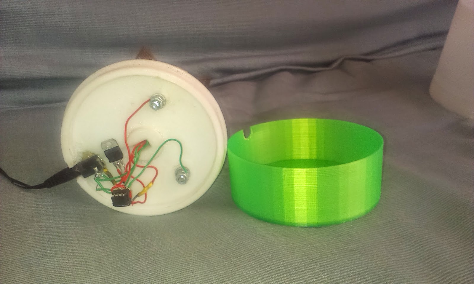
available from hobbytronics; With this, together with two bolts I was able to make a circuit which used a 240v mains power adapter supplying 7v into a 7805 5v voltage regulator so I was able to switch on the LED's on and off. With the base I needed to make the hole for the wire more open and the inside area near the opening a bit more shallow so able to "hot glue" the power socket to the base and the lamp will stand level and straight, rather than produce a PCB or use the surface mount version of the IC, which would have made the electronics smaller and thinner. I soldered the parts directly under the base, which needed me to produce another 3D printed part to extend the height of the base, this can been seen in the photos as the green part.

Testing and Use
As I wanted the best amount of light, I placed 2 of the LED's in parallel with one series resistor on the output pins, so had a total of 4 LED's which gave a current draw of 27mA and voltage of 3.2v across the LED. I found though testing the touch points that this current load was too much for the IC as it's max current output was 25mA. It didn't switch the LED's off; So I decided to just have one LED attached to output pin, which improved the switching.The lamp gives off a fair amount of light but I have found that if left on for a while it can take a test lead from a continuity tester to switch off the light, maybe there is not enough capacitive energy to make the IC switch.Further Development
This could developed further to use a micro-controller and have a USB connection to enable it's user to charge a phone/tablet while it sits on the bedside table. Also placing the bolts on copper and glass pads could increase the capacitive energy so that the IC is able to switch more reliability, currently one output works better than the other. Might have been damaged with the overload of 2 LED's asking for 40mA.Also using a PCB would improve the switching action of the IC rather than bare soldering. As it has been noticed during use that the LED's flicker which could indicate a loose connection or stray static/noise which causes the IC output pin to float.
Thingiverse Profile OricTosh contains links and information about the design files used.
Please comment below or contact me if you spot any errors or required further information
No comments:
Post a Comment